Application Note: Laserdiode-Connections
Related Products: All PicoLAS short pulse driver
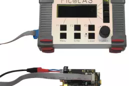
The connection of the laser diode to any of the PicoLAS short pulse drivers is very critical. A wrong connection, the wrong decision about the connection cable etc. will result in slow rise times. This application note shows the measured effects of different connections to the laser diode in respect to the rise times. The used driver is a LDP-V 50-100.
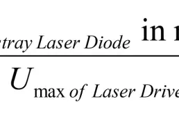
The parasitic stray inductive behavior is the most important influence of the cables. Due to the skin effect, copper thickness is not relevant for short pulses.
Connection type
Current
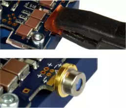
Setup image
Current risetime
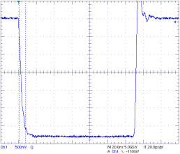
1
A short immediately at the output of the driver with a low impedance ribbon. Make sure that this is recommended in the manual.
Same values can be achieved with a diode connected directly to the unit.
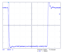
approx. 3,5ns
2
Laser diode with self made stripline.
Length: 100 mm
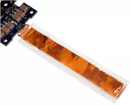
approx. 7ns
3
A laser diode with long legs.
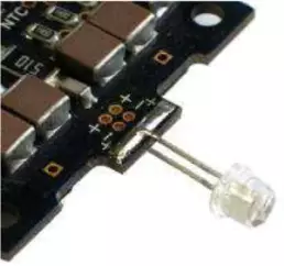
A laser diode with long legs.
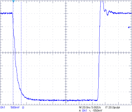
4
Laser diode with round litz wires.
Length: 100 mm
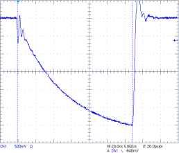
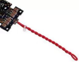
> > 130ns