Application Note: LDP-V xx-100 with the PLCS-21 and PLB-21
Related products: LDP-V 03-100, LDP-V 50-100, LDP-V 80-100, LDP-V 240-100, PLCS-21, PLB-21, LDP-V Kit
This application note describes briefly how to connect a PLB-21 via the PLCS-21 to the different LPD-V series laser diode drivers.
- The PLCS-21 acts as a function generator and a RS-232 translator.
- The PLB-21 is a human interface that allows an easy evaluation and testing, you can easily modify operation parameters of your laser diode.
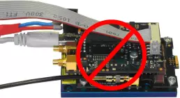
The PLB-21 can not be connected to any LDP-V directly.
What to do?
Picture
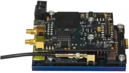
Unpack your driver.
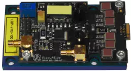
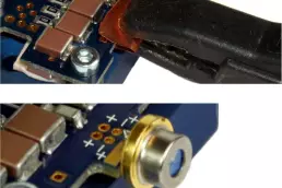
Connect the current monitor cable to the current monitor SMC socket on your driver.
Connect the current monitor cable to the current monitor SMC socket on your driver.
Cables are part of the LDP-V Kit.
Refer to the scope scaling printed beneath the socket or stated in the datasheet.
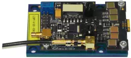
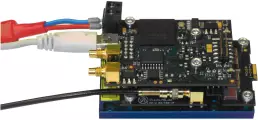
Plug the PLCS-21 onto the top of the LPD-V driver and fix it with three M3 screws (delivered with the PLCS-21).
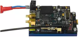
Connect the leads of the power supply unit to the PLCS-21.
You may take the wall plug converter that is part of the LDP-V Kit for powering the device.
Controlling
Option 1:
Connect the driver via USB to a PC.
Please refer to the PLCS-21 manual for the terminal settings.
The LDP-V is powered through the PLCS-21.
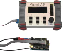
Option 2:
You can connect the PLB-21 onto the PLCS-21.
The PLB-21 and the LDP-V are powered through the PLSC-21.
Important note
Never connect both, USB and PLB-21, at the same time. In this case the PLB-21 would be electronically disconnected and state that it is “waiting for a device”.